7 July, 2025
How to Connect 2 Inverters in Parallel: Step-by-Step Guide for Solar Systems
In large-scale or scalable photovoltaic (PV) systems, the output power of a single inverter is limited due to constraints such as power switch device capacity. To meet the demand of higher power loads, it is common practice to connect multiple inverters in parallel to combine their output power—an effective solution for achieving higher overall system capacity.
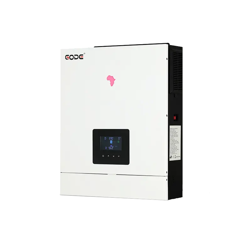
This article takes the GODE 5.6KW-01P solar inverter as an example to systematically explain how to perform a parallel connection of two inverters. It covers preparation, wiring procedures, communication configuration, common mistakes to avoid, and summarizes the pros and cons of inverter parallelization—helping users build a stable, efficient, and expandable PV power system.
1. Preliminary Checks and Preparation
1.1 Verify Inverter Compatibility
Using GODE 5.6KW-01P as an example:
Inverter A: 5.6KW-01P
Inverter B: 5.6KW-01P
Ensure both solar inverters are of the same model and specifications, especially with consistent voltage, current, and frequency ratings. Incompatibility may lead to system failures or equipment damage. The GODE 5.6KW-01P supports up to 6 units in parallel, using RS485 or CAN communication protocols.
We recommend using inverters from the same brand, model, firmware version, and rated power to maximize compatibility and system efficiency.
1.2 Prepare Required Cables and Tools
Sufficient length and gauge of AC cables, communication lines, grounding wires, etc.
Tools: screwdrivers, wrenches, electrical tape, multimeter, and other commissioning tools.
2. Step-by-Step Inverter Parallel Operation
Step 1: Install Communication Cables
- Define the master inverter (Master) and the slave inverter (Slave)
- Use RS485, CAN bus, or manufacturer-specific ports to interconnect the two inverters
- For RS485: use a daisy-chain configuration and add 120Ω termination resistors at both ends for stable communication
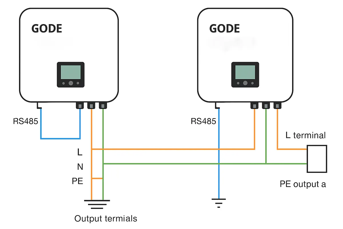
Step 2: Connect Inverter Output Terminals
Connect the output terminals of both inverters with correct phase sequence and polarity. Typical inverter output labels include “L” (Live), “N” (Neutral), and “PE” (Earth). Ensure phase consistency to avoid circulating current (loop current) issues.
- Inverter A Live (L) → Distribution box L terminal
- Inverter B Live (L) → Same L terminal
- Inverter A Neutral (N) → Distribution box N terminal
- Inverter B Neutral (N) → Same N terminal
- Ground terminals of both inverters → Common grounding point
Wiring Standards:
- Use compatible terminals for secure and reliable connections
- All inverters should share the same grounding system to prevent interference or leakage risks
Step 3: Connect to Battery Bank (if applicable)
Connect the output terminals of both inverters with correct phase sequence and polarity. Typical inverter output labels include “L” (Live), “N” (Neutral), and “PE” (Earth). Ensure phase consistency to avoid circulating current (loop current) issues.
- If the system includes energy storage, connect both inverters to the same battery bank
- Install battery isolators, fuses, or breakers for safety
- Ensure battery voltage matches the inverter input range, or startup failure/damage may occur
Step 4: Connect PV Modules
- Option A (recommended): Connect each inverter to a separate solar PV array
- Option B: Use a combiner box to evenly distribute PV strings across both inverters
- Monitor MPPT input current to avoid overload
Connect the output terminals of both inverters with correct phase sequence and polarity. Typical inverter output labels include “L” (Live), “N” (Neutral), and “PE” (Earth). Ensure phase consistency to avoid circulating current (loop current) issues.
Step 5: Power-On and Test
- Double-check all wiring
- Power on the master inverter first, verify voltage/current/frequency output
- Power on the slave inverter and ensure synchronization
- Confirm in the monitoring interface that both inverters are in parallel mode and working in coordination
Step 6: Load Testing
- Connect the system to real loads (motors, lights, etc.)
- Observe for stable operation, absence of alarms, voltage spikes, or inverter faults
- Check whether current sharing between inverters is balanced
- If anomalies occur, inspect communication setup, voltage consistency, and cable quality
3. Common Mistakes to Avoid in Inverter Parallel Setup
Mixing Different Brands or Firmware Versions
Issue: Using inverters with different models, brands, or voltage levels may cause uneven load sharing, inefficiency, or damage
Solution: Always use identical models with the same firmware and specifications
AC Phase Connection Errors
Issue: Incorrect wiring between phase and neutral, or loose terminals, can result in malfunction or reduced efficiency
Solution: Turn off all power before wiring; double-check terminal markings; ensure firm, insulated, and correct connections
Skipping Communication Configuration
Issue: Without proper communication setup, the inverters can’t exchange data, leading to instability
Solution: Use RS485, CAN, or the manufacturer’s dedicated interfaces, configure master-slave roles, and verify communication status
Insufficient Ventilation or Tight Installation
Issue: Installing inverters in poorly ventilated, confined spaces may cause overheating and performance degradation
Solution: Allow adequate spacing for airflow, cooling, and maintenance to ensure long-term reliable operation
4. Advantages and Disadvantages of Parallel Inverter Systems
Mixing Different Brands or Firmware Versions
4.1 Advantages
Increased Capacity and Output:
Multiple inverters connected in parallel combine their power, e.g., two GODE 5.6KW-01P inverters deliver 11.2kW, ideal for high-consumption households.
Improved Reliability:
In case one inverter fails or is under maintenance, others continue operating to maintain power supply.
Scalability:
Easily expand the system by adding more inverters without redesigning the whole infrastructure, saving time and cost.
Extended Lifespan:
Load is distributed among units, reducing stress on individual inverters and increasing their service life.
4.2 Disadvantages
Higher Cost:
Two inverters are usually more expensive than one of equal capacity. Additional cables and accessories add to the cost.
Maintenance Complexity:
More devices mean more points of failure and longer troubleshooting times.
Greater Control Complexity:
Parallel operation requires precise current sharing control to prevent circulating currents. Existing methods like current detection, master-slave, decentralized logic, or droop control are still imperfect—posing risks of losses, instability, or power interruptions.
While inverter parallel operation offers significant advantages in capacity, reliability, and scalability, it demands high standards in inverter selection, communication setup, wiring accuracy, and system coordination. By carefully following standard procedures and using compatible components, users can minimize risks such as circulating current or voltage imbalance and ensure safe, long-term parallel operation.
For projects involving multi-inverter systems, we recommend choosing inverters with native parallel support, complete communication interfaces, and thorough documentation to reduce technical complexity and ongoing maintenance costs.
share